- • Requirements for the controlled devices
- • Dashboards, Zones, Categories
- • Simple thermostat with hysteresis
- • Simple Heating management using Weekly schedule and Presence switch
- • Power limiting
- • Notification on high temperature (DEPRECATED)
- • Configuring hysteresis control via Equation Smart Rule
- • PID Temperature regulation
- • PID Cascade
- • Regulation of Boiler Cascade
- • Equithermic regulation
- • Heating control in high electricity tariff via load management tariff indicator input
- • Heating and Cooling modes
- • Editing multiple devices at once
- • Setting the response speed of push buttons
- • Integrate multiple control units Core
- • Safe values
- • How to combine two daily schedules in one day
- • Linking devices together
- • Device log
- • Using statistic values in Smart Rules
- • Hot water circulation pump control
- • Exporting data from TapHome into Google Spreadsheet using Integromat
- • Exporting device descriptions
- • 2025
- • 2024
- • 2023
- • 2022.2
- • 2022.1
- • 2021.3
- • 2021.2
- • 2021.1
- • 2020.1
- • 2019.1
- • 2018.1
- • 2017.1 - Blinds automation - angle control update
- • 2017.1 - Blinds automation - Depth of sun rays
- • 2017.1 - Charts updated
- • 2017.1 - Core update from the app
- • 2017.1 - Double click and triple click
- • 2017.1 - Expose devices
- • 2017.1 - Multi-value switch
- • 2017.1 - Permissions
- • 2017.1 - Replace module action
- • 2017.1 - Set to Automatic mode - "Push buttons event" Smart Rule
- • 2017.1 – Daily schedule Smart Rule
- Documentation
- Wiring info and examples
- Examples of Modbus RTU cabling
Examples of Modbus RTU cabling
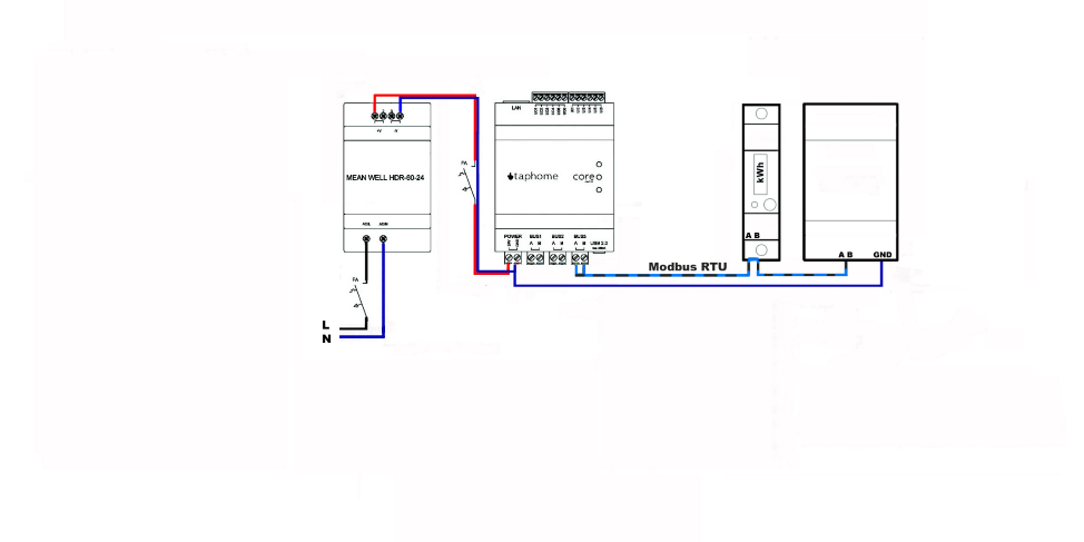
For devices connected to the Modbus RTU line, different rules apply when connecting devices. The devices are connected using two A / B wires. It is not necessary to implement a GND connection from a 24V DC source. Namely, if the devices require this connection in the manufacturer's conditions, the requirement must be implemented. Because manufacturers universally set their peripherals to address 1, I assign each device a sequential 1-250 identification address when sequentially connected. Devices with the same address do not work on the system. It is recommended to terminate the bus with a 120R resistor. Some products already have this resistor installed automatically, in which case it no longer needs to be retrofitted to the connection terminals. The devices that communicate with the Modbus RTU protocol are mostly recuperation, air conditioning, energy counting devices, relay output and input modules.
For proper communication with Modbus, all peripherals must have the same communication protocol set with speed, parity and stop bits. Otherwise, the devices will not function as a whole. Always check the manuals of the peripherals you connect for the correct settings and the possibility of changing the settings of the communication parameters.
For classic RS485 and Modbus RTU distributions, a cable type meeting the EIA RS-485 requirements with an impedance of 120R is prescribed for industrial distributions. All you have to do is create a bus for our control blocks using Cat5E, Cat6, Cat6A and others. RS-485 certified cabling is not required. Shielded cabling as a whole or separately in individual pairs is also not strictly prescribed. In cables that are not individually shielded in pairs, it is not recommended to run two different buses such as RS-485 and LAN 100/1000MBit, or other bus distribution EZS, EPS, Modbus RTU, etc.
