- • Requirements for the controlled devices
- • Dashboards, Zones, Categories
- • Simple thermostat with hysteresis
- • Simple Heating management using Weekly schedule and Presence switch
- • Power limiting
- • Notification on high temperature (DEPRECATED)
- • Configuring hysteresis control via Equation Smart Rule
- • PID Temperature regulation
- • PID Cascade
- • Regulation of Boiler Cascade
- • Equithermic regulation
- • Heating control in high electricity tariff via load management tariff indicator input
- • Heating and Cooling modes
- • Editing multiple devices at once
- • Setting the response speed of push buttons
- • Integrate multiple control units Core
- • Safe values
- • How to combine two daily schedules in one day
- • Linking devices together
- • Device log
- • Using statistic values in Smart Rules
- • Hot water circulation pump control
- • Exporting data from TapHome into Google Spreadsheet using Integromat
- • Exporting device descriptions
- • 2025
- • 2024
- • 2023
- • 2022.2
- • 2022.1
- • 2021.3
- • 2021.2
- • 2021.1
- • 2020.1
- • 2019.1
- • 2018.1
- • 2017.1 - Blinds automation - angle control update
- • 2017.1 - Blinds automation - Depth of sun rays
- • 2017.1 - Charts updated
- • 2017.1 - Core update from the app
- • 2017.1 - Double click and triple click
- • 2017.1 - Expose devices
- • 2017.1 - Multi-value switch
- • 2017.1 - Permissions
- • 2017.1 - Replace module action
- • 2017.1 - Set to Automatic mode - "Push buttons event" Smart Rule
- • 2017.1 – Daily schedule Smart Rule
- Documentation
- Wiring info and examples
- Serial bus topology recommendations
Serial bus topology recommendations
Method of connecting components in individual types of buses
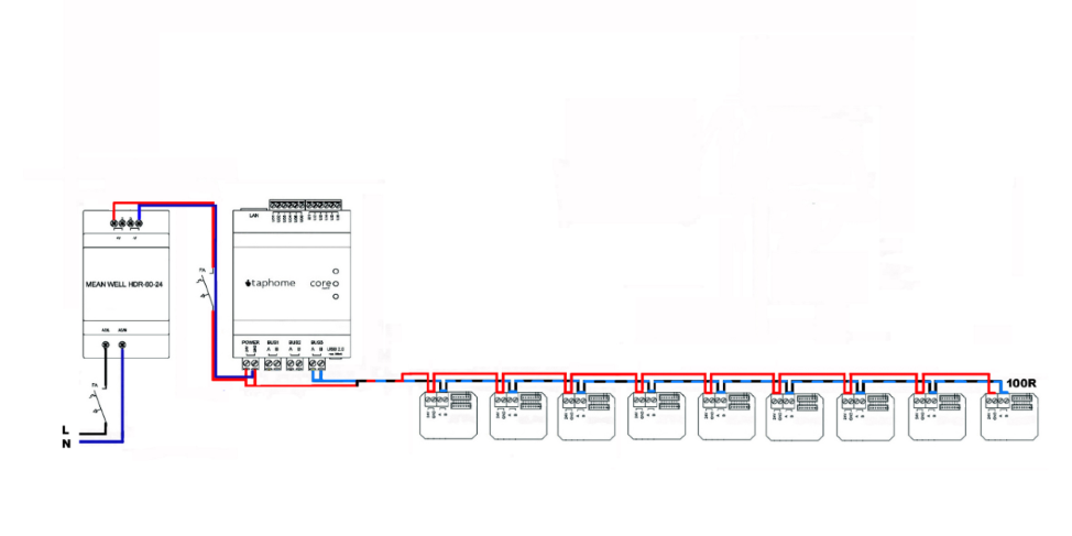
The basic type of bus is the line terminated at the farthest point by a terminator. The ohmic value of the terminator is usually 120R. For longer routes, it can have a value of 100R. The rule of two-wire networks is that there can be a maximum of 31 separate modules on one bus. 32 modules in full is Core. When using our modules, it is not necessary to follow the rule of cabling length distance between two 35-50 cm modules.
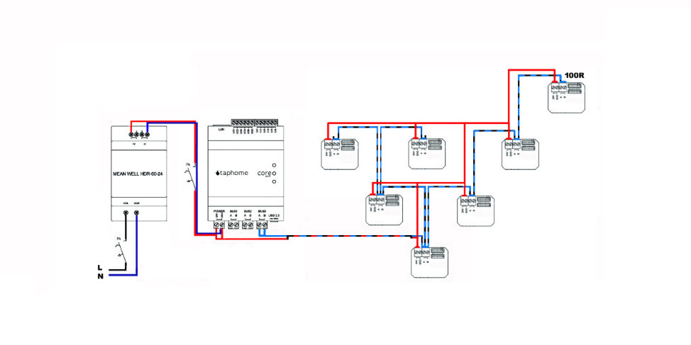
The bus connection by the STROM cabling distribution system can also be used in our devices. The rule of terminating the bus by the terminator at its farthest point also applies here. If you are not sure which point is furthest from such a bus branch, it is not forbidden to use more than one terminator on the last physically connected components. But with branching you need to be careful and minimize it. An undefined condition may occur in which some peripherals will log off the bus, causing a system fault condition.
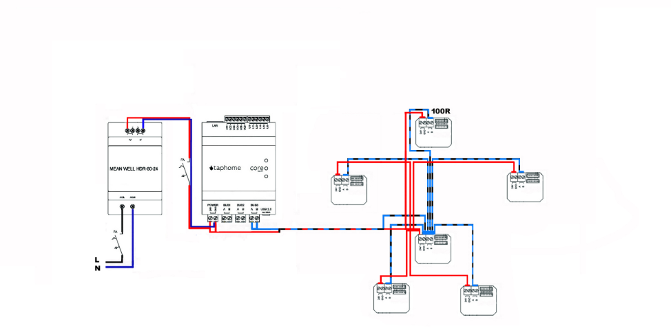
The last option for bus connection is the STAR topology. It is often used in smaller control systems and single-family homes, where there are short distances between devices. It is necessary to monitor the directions of lines, concurrencies and other necessary requirements for the bus. The system may be more prone to communication failures and interference.
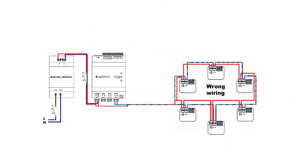
Circular topology is strictly forbidden on all two-wire communication buses. If you have the cabling ready in this way, you will not connect one of the ends to the Core output, but you will connect a 120R terminating resistor to it. In the event that the cabling is inadvertently broken over time, you can effectively obtain the connection of two parallel lines. This will keep the communication and power supply of the control modules functional.
Not only in the connection of the line, it is possible to use several DC sources for control modules at greater distances. However, the rule must be followed that the GND of these resources will be interconnected. The need to use another source is based on the distance project and also on the type of communication cable used.
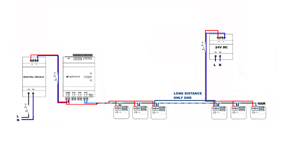
For classic RS485 and Modbus RTU distributions, a cable type meeting the requirements of EIA RS-485 with an impedance of 120R is prescribed for industrial distributions. For our control blocks, it is sufficient to create a bus using Cat5E, Cat6, Cat6A and more. Cabling certified for RS-485 networks is not required. Likewise, shielded cabling as a whole or separately in individual pairs is not strictly prescribed. In cables that are not individually shielded in pairs, it is not recommended to run two different buses, such as RS-485 and LAN 100 / 1000MBit, or other bus distributions for burglar alarms, EPS, Modbus RTU and the like.