Surge Protection
Essential surge protection for RS-485 and Modbus buses in exterior areas. Includes protection for power supplies and current loops. Prevents voltage damage with multi-stage circuits.
When to use surge protection
Surge protection (voltage surge protector) for the RS-485 bus is recommended in these cases:
- The bus is run through the exterior
- The bus passes through an area outside the protective zone of the lightning protection system
How it works
Surge protection, unlike a bus isolator, diverts the induced voltage to the PEN/PE terminal and thus protects the input circuits of your devices.
Power supply protection
Power supply in a protected area
When using the circuit shown in the attached diagram, there is no need to protect the positive terminal of the power supply if the source is located in a protected area.
Power supply in an unprotected area
If the source is located in an unprotected area, the following are required:
- Surge protection for the 24 V DC distribution
- Type C protection on the AC input side
The actual down-conductor design depends on the cross-section of the LV distribution feeder cable and the possibility of grounding the system.
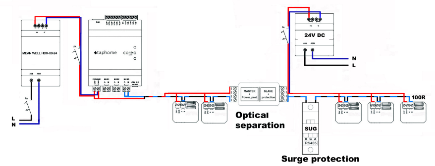
Wiring diagram
In the attached diagram, surge protection is used only on the supply to the remote section located outdoors.
Warning: This is only a partial solution for protecting the bus. For complete protection, see the section below.
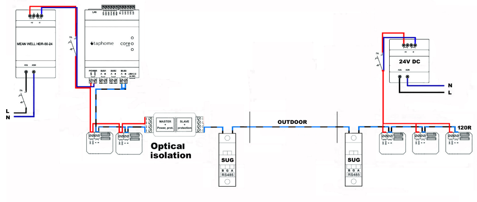
Complete protection of the bus
A fully correct protection solution requires two surge protection devices in the following cases:
When is full protection required
The bus passes through sections that:
- Are and subsequently are not in the protective zone of lightning protection systems
- Do not have the ability to absorb the energy field created by atmospheric discharges
Placement of protectors
Surge protection devices are installed at the entry points of conductors into protected zones.
Important: This applies regardless of whether an optical isolator is used on the bus.
Modbus bus protection
When to use
For a Modbus bus run through exterior areas outside the protective zone of the lightning protection system, we recommend using surge protection.
Power protection
When using the circuit shown in the attached diagram, there is no need to protect the positive terminal of the power supply since it is not used.
Standards requirements
When designed properly, one should not neglect the risk of electromagnetic impulses from atmospheric lightning discharges in accordance with standard STN EN 62305.
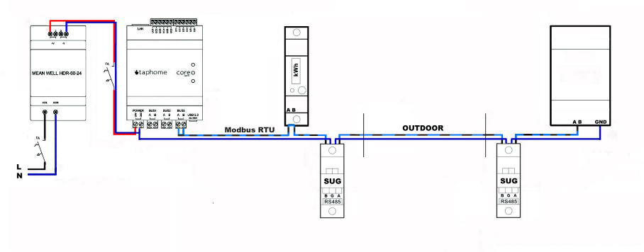
Wiring diagram
The attached diagram shows the full protection of the Modbus bus line, equipped with surge protection on both ends of the bus conductor.
Surge protection for temperature measurement
Measurement using resistance sensors (Pt100)
When measuring temperature using resistance sensors (e.g. Pt100), consider:
- The ohmic component of the supplementary cables
- Damping resistors of protective devices
Impact on measurement accuracy
Pay attention to measurement accuracy!
In the case of two-wire measurement, the resistance value of the SPD can distort the measured result.
Example of error:
- Sum of damping resistors: 4 Ω
- Error in measurement at 0°C: 4% (104 Ω instead of 100 Ω)
Solution
Two-stage protective circuits are available in a version without damping resistors to minimize the SPD’s impact on measurement accuracy.
Surge protection for current loops
4–20 mA signal
Measured values are transmitted using the standardized 4–20 mA signal, which is used especially in applications with longer conductors.
Advantages of current-loop transmission
- The cable’s ohmic resistance does not affect the current carrying the measured value
- Two signal conductors are used
- No additional reference potential is required
- They are carried in an isolated state from the earth potential
Protection
Protection at both ends is required!
To protect this type of application from transients, an SPD is required at both ends.
SPD construction
The respective SPD is equipped with a multi-stage protective circuit that provides protection against:
- Transient voltages in normal operation between signal conductors
- Common-mode voltage to ground at both ends