- • Requirements for the controlled devices
- • Dashboards, Zones, Categories
- • Simple thermostat with hysteresis
- • Simple Heating management using Weekly schedule and Presence switch
- • Power limiting
- • Notification on high temperature (DEPRECATED)
- • Configuring hysteresis control via Equation Smart Rule
- • PID Temperature regulation
- • PID Cascade
- • Regulation of Boiler Cascade
- • Equithermic regulation
- • Heating control in high electricity tariff via load management tariff indicator input
- • Heating and Cooling modes
- • Editing multiple devices at once
- • Setting the response speed of push buttons
- • Integrate multiple control units Core
- • Safe values
- • How to combine two daily schedules in one day
- • Linking devices together
- • Device log
- • Using statistic values in Smart Rules
- • Hot water circulation pump control
- • Exporting data from TapHome into Google Spreadsheet using Integromat
- • Exporting device descriptions
- • 2025
- • 2024
- • 2023
- • 2022.2
- • 2022.1
- • 2021.3
- • 2021.2
- • 2021.1
- • 2020.1
- • 2019.1
- • 2018.1
- • 2017.1 - Blinds automation - angle control update
- • 2017.1 - Blinds automation - Depth of sun rays
- • 2017.1 - Charts updated
- • 2017.1 - Core update from the app
- • 2017.1 - Double click and triple click
- • 2017.1 - Expose devices
- • 2017.1 - Multi-value switch
- • 2017.1 - Permissions
- • 2017.1 - Replace module action
- • 2017.1 - Set to Automatic mode - "Push buttons event" Smart Rule
- • 2017.1 – Daily schedule Smart Rule
- Documentation
- Configuration
- Heating / Cooling
- Regulation of Boiler Cascade
Regulation of Boiler Cascade

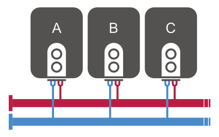
Use this setup if you want to achieve desired temperature of hydronic circuit using 2 or more boilers connected in cascade.
In the example scenario, we will show configuration for 3 boilers, that can be controlled by digital outputs.
Preparations
You should already have following devices defined:
Thermostat with temperature of returning water, measured on the pipe
Thermostat |
|---|
 |
Digital outputs for each boiler (Boiler A, Boiler B, Boiler C)
| Boiler A | Boiler B | Boiler C |
|---|---|---|
 |  |  |
Create virtual Analog Output that will be used as a variable for calculating overall heat output.
Overall Output |
|---|
 |
Basic configuration
Create Smart Rule Temperature PID Controller that will calculate Overall Output based on difference in Thermostat Set point and Actual temperature
Input device | → Smart Rule → | Output device |
|---|---|---|
Thermostat | → PID Controller→ P = 2 | Overall Output |
Based on overall output ranges, 3 (or more) boilers will be turned on
Configuration for mode where priority of boilers is: Boiler A → Boiler B → Boiler C
Input device
| → Smart Rule →
| Output device
|
|---|---|---|
| <1% | -- | -- |
| >1% | Equation: Minimum duration: 5min | TRUE: Turn on Boiler A |
| >45% | Equation: Minimum duration: 5min | |
| >90% | Equation: Minimum duration: 5min |
|
Cycling of boilers
In order to achieve even usage of boilers, extra configuration needs to be applied.
Create Multi-value switch with N+1 states, where N is number of boilers. Last state can be defined as Heating Inactive system with zero heating.
Name: Boiler Priority
States:
- Priority A (Boiler A → Boiler B → Boiler C)
- Priority B (Boiler B → Boiler C → Boiler A)
- Priority C (Boiler C → Boiler A → Boiler B)
- Heating Inactive
Create Smart Rule Sequencer that will rotate priorities (A → B → C → A → ... )
Input device | → Smart Rule → | Output device |
|---|---|---|
Virtual push button to start the sequencer | Sequencer (/) Rotate sequence | Boiler Priority |
Define separate set of smartrules limited for each Boiler Priority. See Smart Rules for Priority A in table below:
Input device
| → Smart Rule →
| Output device
| Limiting Condition |
|---|---|---|---|
| <1% | -- | -- | |
| >1% | Equation: | TRUE: Turn on Boiler A | Type: Multi-Value Switch
|
| >45% | Equation: | TRUE: Turn on Boiler B | Type: Multi-Value Switch
|
| >90% | Equation: | TRUE: Turn on Boiler C | Type: Multi-Value Switch
|
Similar set of Smart Ruless should be applied with Limiting Condition for Priority B and Priority C:
Input device
| → Smart Rule →
| Output device
| Limiting Condition |
|---|---|---|---|
| <1% | -- | -- | |
| >1% | Equation: | TRUE: Turn on Boiler B | Type: Multi-Value Switch
|
| >45% | Equation: | TRUE: Turn on Boiler C | Type: Multi-Value Switch
|
| >90% | Equation: | TRUE: Turn on Boiler A | Type: Multi-Value Switch
|
Input device
| → Smart Rule →
| Output device
| Limiting Condition |
|---|---|---|---|
| <1% | -- | -- | |
| >1% | Equation: | TRUE: Turn on Boiler C | Type: Multi-Value Switch
|
| >45% | Equation: | TRUE: Turn on Boiler A | Type: Multi-Value Switch
|
| >90% | Equation: | TRUE: Turn on Boiler B | Type: Multi-Value Switch
|