
Modbus
Introduction to Modbus
Modbus is a simple communication protocol, often used to integrate HVAC equipment. It uses master-slave communication, when several devices can be connected to the common bus, each must have a unique Slave ID, and the master device always queries the individual slave devices that respond to it.
Master - slave topology
In most cases, TapHome is used in the mode where the Core control unit is Modbus Master, and the connected devices are Modbus Slave. This is set in the Hardware section → Modbus RTU or Modbus TCP. However, it is also possible to use the opposite direction, when TapHome Core provides some other superior system with information about its devices. It is defined in section Expose devices → Modbus RTU or Modbus TCP.
Physical layers
Modbus can communicate through different physical layers:
- via a serial line, typically RS485. This is referred to as Modbus RTU
- over the LAN network via the TCP/IP protocol
- over the LAN network via the UDP protocol - currently not supported by the TapHome system
Modbus registers
Modbus defines 4 types of registers:
Register | In short | Access | Size | Function codes |
|---|---|---|---|---|
| Holding Registers | H | Read-write | 16-bits | Read: 03, Write multiple: 16 (0x10) |
| - Write Single Holding | SH | Read-write | 16-bits | Write single: 06 |
| Coil (Discrete Output Coils) | C | Read-write | 1-bit | Read: 01, Write multiple: 15 (0xF) |
| - Write Single Coil | SC | Read-write | 1-bit | Write single: 05 |
| Discrete Input Contacts | D | Read-only | 1-bit | Read: 02 |
| Analog Input Registers | A | Read-only | 16-bits | Read: 04 |
The register number is 16 bits, that is, it can have a value from 0 to 65535. Operations can be performed on the registers:
- reading multiple registers
- registration of one register
- registration of several registers
Some Modbus implementations add additional commands: report slave id, bit masking, write and read at once, etc., but these are not supported by TapHome.
Information about what is stored in which register and in what format is part of the equipment documentation provided by the equipment supplier or manufacturer. An example of Modbus documentation from a Modbus device supplier:
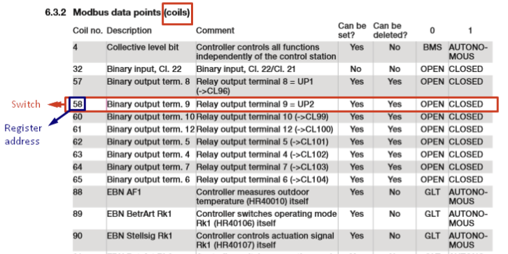
Register type C (Coil), index 58, since it has only 2 values (open / closed) and allows in addition to reading and writing, the appropriate type of TapHome device is Digital output.
Accelerated instructions for integrating a Modbus device into TapHome
- Connect the device to the appropriate bus (for Modbus RTU and ASCII) or to the LAN (for Modbus TCP). For a TCP device, make sure it is on the same network as the TapHome Core controller, for example using Fing (iOS, Android) or IP Scanner (Windows).
- In TapHome → Hardware, add a new Modbus RTU or Modbus TCP interface, and set the communication parameters according to the documentation. For Modbus RTU it is Baud rate, Stop bits, Parity, Data bits, for Modbus TCP it is IP address.
- Find in the Modbus documentation of the device what Slave ID it uses. In the case of Modbus TCP, this is sometimes referred to as Unit ID. If you want to use multiple devices on one bus with Modbus RTU, you must change the Slave ID of each one so that it is unique for the given bus line.
- Communication test - using the Manual operations tool, try to read some information according to the documentation (Modbus table) for the given device. If everything works, you should see a readout.
- If the communication test was successful, create a Module that represents the Modbus device
- Choose which information from the Modbus documentation you want to present in the TapHome system and create the corresponding devices. Start by reading the values (Read script), and in the case of actors, continue by writing (Write script).
- If the basic functions of the device are working, add Error, Warning, or Information definitions to the scripts.
- If necessary, you can also define Service Attributes and Service Actions for TapHome devices and modules
- If everything is tuned and communicating correctly, export the Module to an XML file so you can use it next time. You can also contribute to the community at github.com/taphome-official/modbus_templates
Implementation in TapHome
This documentation is intended for the scenario where the TapHome Core control unit is a Modbus master, and the physical devices that are added to the Hardware → Modbus RTU / TCP section are Modbus slaves.
Hierarchy
Interface
Hardware → Modbus RTU: devices are connected on some BUS, the basic parameters of RS485 transmission are defined, such as baudrate, parity, stop bits, or whether the data is ASCII or binary. Only devices with the same communication settings can be connected on this bus. Also, correct communication can only work if the A and B cables are connected correctly. Hardware → Modbus TCP: devices are connected on the same LAN as the Core control unit. One TCP port is defined, which is common to all devices connected to this interface.
Module
An interface can contain one or more modules, which in most cases cover communication with the entire physical device. From a configuration point of view, the Module defines the unique Slave ID of the connected device for Modbus RTU, and additionally the IP address for Modbus TCP.
Device
Represents a specific control element or sensor in the TapHome system. It must always be part of one parent Module.
Example
5 air conditioning units connected on one bus, use a common Modbus RTU interface, which defines the bus port, baudrate, and other communication parameters. The interface contains 5 modules, each of which represents one air conditioning unit with a unique Slave ID. Each module has defined devices under it, such as a thermostat, cooling / heating mode, fan power or tilting of the slats. Individual devices have defined commands for reading and/or writing Modbus values.
Supported devices:
- Digital output
- Analog output
- Thermostat
- Multi-value switch
- Temperature sensor
- Electric meter
- Status contact
- Button
- A variable
Scripts for reading and writing Modbus values
TapHome devices communicate with physical Modbus devices using scripts.
For communication with Modbus devices, scripting sections are defined on them:
- Initialize script: is run when the device starts (e.g. after the control unit is restarted)
- Read script: setting values of global variables or reading error states
- Read Value script: script for reading a specific value (quantity) from a Modbus device (e.g. set temperature on the thermostat or measured temperature on the thermostat)
- Write Value script: write the value to the Modbus device
Functions for communication with Modbus devices
MODBUSR (Modbus Read) Function for reading register from Modbus. Depending on the data type, it can be 1 register (for 16-bit data types), 2 registers (for 32-bit data types), or more registers (for String data types)
MODBUSR(register_type, register_address, data_type, [OPTIONAL: number_of_characters if data_type=String])
Example: MODBUSR(H, 20, Int16)/100
Read the H register number (or address) 20, and interpret it as a 16-bit Integer (a whole number with a +- sign). Finally, divide this value by the number 100 (shift the decimal point 2 places to the left).
The registry address can also be entered in hexadecimal format, e.g. the value 20 can be written as 0x14.
MODBUSW (Modbus Write)
MODBUSW(register_type, register_address, data_type, value_to_write)
Example: MODBUSW(H, 20, Int16, Te * 100)
In the register H with address 20, write the value of the variable Te multiplied by the number 100 (shifting the decimal point by 2 to the right).
MODBUSWNE (Modbus Write if Not Equal)
The same as MODBUSW with the difference that it reads the value from the register before writing, and writes it only if the written value is different from the read one. The whole operation takes longer, and its typical use is when setting the properties of a Modbus device, where the configuration is written to the EEPROM memory with a limited number of writes.
The functions MODBUSR, MODBUSW and MODBUSWNE can only be used in Modbus scripts. If used in other scripts, they are considered an error.
Modbus data types
The contents of the registers are defined in the modbus table. Since the size of one Modbus register is 16 bits, 16-bit Int16 or UInt16 values are most often used, and decimal places are counted down by divisions of 10 or 100. But some Modbus devices also use 16-bit registers with floating-point numbers (Float), or they have a changed bit order (big endian, little endian), they write one number in two registers (32 bit variations). Sometimes the easiest way to find out the correct data type is to use the utility directly in the TapHome application (Manual Operations), where you can load 1 or more registers and dynamically switch the data type.
- Int16 (-32.768 to 32.767)
- Uint16 (0 to 65,535)
- Int32 (-2,147,483,648 to 2,147,483,647)
- Uint32 (0 to 4,294,967,295)
- Float (IEEE 754 Single precision floating point)
- Bool 0 = false, 1 = true
- BigEndianInt16 = Int16
- LittleEndianInt16
- BigEndianUint16 = Uint16
- LittleEndianUint16
- BigEndianInt32 / BigEndianInt32ByteSwap
- LittleEndianInt32 / LittleEndianInt32ByteSwap
- BigEndianUint32 / BigEndianUint32ByteSwap
- LittleEndianUint32 / LittleEndianUint32ByteSwap
- BigEndianFloat / BigEndianFloatByteSwap
- LittleEndianFloat / LittleEndianFloatByteSwap
-
String
BCD format can also be used, thanks to the functions TOBCD() and FROMBCD()
Update and Poll Interval
Each device in the Modbus interface has a defined Poll Interval attribute. This determines how often the TapHome control unit should poll for new Modbus device values. Modbus communication is of the Master-Slave type, and thus information from the Modbus device can reach TapHome only when TapHome requests it. The longer the Poll Interval, the later the value in TapHome is refreshed. Too short a Poll Interval may mean that TapHome will be unnecessarily burdened by obtaining unnecessary values, and may not have time to serve all devices within the given time interval. For example, with Modbus RTU and lower Baud Rate speeds, e.g. 9600, one query / response can take tens of ms. For thermometers, in most cases, an interval of 15000ms (15s) is sufficient, for buttons, on the contrary, as little as possible, e.g. 50 ms. Some Modbus devices expect the master to periodically write the current value to the register. This is what the Periodic Write attribute is for.
Definition of error states from scripts
In some scripts it is possible to define an error / warning / information on the device, based on the information read from the device's Modbus registers. These messages are displayed in TapHome in the same way as internal TapHome error messages. Optionally, a numeric error code can be added to the error message if practical for servicing the Modbus device.
Only one error message with no code or only one error message per error code can be defined on the device.
ADDERROR(), ADDWARING(), ADDINFO()
ADDERROR([Optional: custom_code], text)
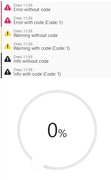
Example: in the Read Script section of the Analog Output device there is a code:
ADDERROR("Error without code");
ADDWARNING("Warning without code");
ADDINFO("Info without code");

ADDERROR(1, "Error with code");
ADDWARNING(1, "Warning with code");
ADDINFO(1,"Info with code");
...which is reflected on the device by messages:
Service attributes and actions
In addition to a value (or multiple values, such as a Thermostat) from a connected Modbus device, TapHome modules and devices can also read service attributes or perform service actions. These are then not accessible on the desktop for other users of the system, but serve only for more detailed information about the Modbus device, without unnecessarily overloading the system with a large number of variables and actions.
Service attributes are displayed in the service settings of the TapHome module or device. Typically, they are used to display information about the device, such as Model, Serial Number, Firmware Version, Hardware Version, Time since last reboot, etc. This is useful information from the point of view of servicing a Modbus device, but it does not make sense to create separate TapHome devices for them.
Service actions are displayed in the service settings of the TapHome module or device, at the very bottom as buttons. When pressed, they perform a preset Modbus action that writes the required information to the register. Example of use: Setting or changing the Slave ID, Replacing the filter, Setting the counter to the required value, Resetting the device and the like.
Scripts and auxiliary variables on the module
Module global variables
Variables defined on a module are usable in all scripts on the module and are shared with all devices assigned to that module.
Init script
Optional. Runs when the module starts. If it is filled and has not yet run, no further scripts will be allowed.
💬 Return value: ignored
⚙️ Access to variables: module global variables
⚠️ Error status support: no
Read script
Runs every time a module is polled.
💬 Return value: ignored
⚙️ Access to variables: module global variables
⚠️ Error status support: yes
Write script
Running:
- when changing the device variable
-
if the "Periodic Write" attribute is enabled, it starts automatically
💬 Return value: ignored
⚙️ Access to variables: global variables of the module, values of devices belonging to the given module (be careful, they are not global device variables - the module script does not have access to them). This is used in the case when the values of several devices of the given module need to be written into one register.
⚠️ Error status support: no
Service attributes
Each module can have an unlimited number of service attributes defined. The scripts are executed every time a user (with service privileges) opens the module's service settings screen in the app. They are written at the top, immediately after reading from the Modbus device.
💬 Return value: is displayed as the value of the given attribute
⚙️ Access to variables: module global variables
⚠️ Error status support: no
Service actions
Each module can have an unlimited number of service actions defined. The scripts are started when the user (with service privileges) opens the app on the module's service settings screen and presses one of the defined buttons with the name of the service action. Each service action is defined by its name, parameters, and execution script.
💬 Return value: ignored
⚙️ Access to variables: global module variables, user-specified parameters
⚠️ Error status support: no
Scripts and helper variables on the device
Global device variables
Variables defined on a device are usable in all scripts defined on that device, and are not usable anywhere outside the device. The device can store its state in them, share between its scripts, and so on.
Init script
Optional. It starts when the device starts. If it is filled and has not yet run, no further scripts will be allowed.
💬 Return value: ignored
⚙️ Access to variables: module global variables, device global variables
⚠️ Error status support: no
Read script
Runs every time the device is polled, before "Read Value Scripts".
💬 Return value: ignored
⚙️ Access to variables: module global variables, device global variables
⚠️ Error status support: yes. Errors concern the entire device (e.g. the entire thermostat, not just its set point value or current temperature value).
Write value script
Running:
- at every value change
- if the "Periodic Write" attribute is turned on, also with every polling
💬 Return value: ignored
⚙️ Access to variables: global variables of the module, global variables of the device, the specific value of the quantity to be written via Modbus to the device.
⚠️ Error status support: no
Read value script
Runs every time a device is polled.
💬 Return value: is automatically assigned as the value of the given device
⚙️ Access to variables: global variables of the module, global variables of the device, the most recently loaded value of the variable, the bark to be read (useful, for example, if the device indicates that it has not yet been loaded, etc.)
⚠️ Error status support: yes. Error messages should refer to the given quantity on the device. For example if the ADDERROR(1, "Sensor not connected") command is in the Read Temperature script in the Thermostat device, the user will see an error message in the app on the thermostat with three pieces of information: Temperature, code 1, text "Sensor not connected".
Service attributes
Each device can have an unlimited number of service attributes defined. The scripts are executed every time a user (with service privileges) opens the device's service settings screen in the app. They are written at the top, immediately after reading from the Modbus device.
💬 Return value: is displayed as the value of the given attribute
⚙️ Access to variables: module global variables, device global variables
⚠️ Error status support: no
Service actions
Each device can have an unlimited number of service actions defined. The scripts are executed when the user (with service privileges) opens the app on the device's service settings screen and presses one of the defined buttons with the name of the service action. Each service action is defined by its name, parameters, and execution script.
💬 Return value: ignored
⚙️ Access to variables: global module variables, global device variables, user-specified parameters
⚠️ Error status support: no
Helpful utilities
Add from template
It allows you to configure Modbus communication with the device without any knowledge of the Modbus protocol or how to configure it in TapHome. Pre-made templates can be found:
- directly in the application: Add from template → select a specific device → fill in the basic information and confirm. All these templates are maintained in a community git project at https://github.com/taphome/modbus_templates and anyone can suggest new mods there. What gets into the apps must be approved directly by the TapHome team
- in your own XML file: Add from template → Add from file. You can create your own XML file that defines the entire template directly on the Modbus module, in the context menu (3 dots on the top right), Save as template action. We will be happy if you help us to expand the number of supported devices and contribute your XML file to the joint community git project.
More info on configuring Modbus communication using templates
Manual Operations
A practical tool for quick initial verification of the Modbus table. Allows:
- load the following X registers into the table from a specific register, and then dynamically switch the read values into different data types
- write the value to the given register
Scan Slave IDs
A common practice when setting up communication with a Modbus device is that the factory default Slave ID is other than 1, and it is not easy to work out the correct number. That's what this utility is for. It can scan the specified Slave ID range by trying to read from the selected register always with the tested Slave ID.
Information about registers
It is located in the lower part of the Modbus module. For each register used, it lists information about:
- The TapHome name of the device that reads or writes to it
- Date and time of the last successful read from the register
- The last value read from the register
- Date and time of the last successful registration in the register
- The last value written to the register
Advanced settings
Prefetch
TapHome creates a list of registers to read from and write to Modbus devices, depending on the set Poll interval. Prefetch is a process thanks to which the control unit prefetches into the buffer the values that it will need during the update. The goal is to minimize the number of requests and round trips. Prefetch is affected by 2 settings:
- Max prefetch register group size (located in the service settings of the module): determines the maximum number of registers that can be read or written via Modbus communication with one request.
- Prefetch mode (adjustable for each device):
- No prefetch. Preloading will not be performed for this device. This means that the values will be read individually and exactly when the script is executed. Example of use: when communicating with a DALI converter, the value of a specific light cannot be read directly, but it must be requested as soon as possible, the converter will prepare it, and only then return it. Any preloading is pointless in this case.
- Isolated prefetch. It preloads several registers at once, but only those that are defined in this device. For example when I need registers 3 and 4 in the thermostat device, registers 1, 2, 5, 6 are used in the other devices, so the request for registers 3 and 4 will be made separately only for these 2 registers. Some Modbus devices require this.
- Normal prefetch. All requested registers from the devices to be restored are tried to be read with the minimum number of requests. In the case of a non-continuous sequence of registers, it also reads registers that are not used, if they were read successfully in the past. Example: Register 99 and 101 are requested. If register 100 was successfully read in the past, and the Max prefetch register group size is 3 or more, it will read 3 registers with one request from register 99. If register 100 is not used anywhere, and has never been successfully read, there is a risk that reading through such a register could return a Modbus exception, e.g. "Illegal data address" as a response to the entire request.
Prefetch can also be influenced directly from the script: If we use the SC or SH register (instead of C or H) when reading, then the value is read one register at a time during the execution of the script, and it is not pulled from the cache memory. Similarly, when writing, if we use SC or SH register (instead of C or H), the value is written one register at a time and by another modbus function. Modbus protocol supports 4 writing functions: writing multiple H, multiple C, writing one H or one C register at a time. Attention: not all devices may support all these functions. In this way, if necessary, reading and writing can be combined together and "one at a time".
TCP Port (Modbus TCP)
In most cases, the default value is 502, but it is possible that some devices listen on a different port.
Read / Write Timeout
The time after which TapHome gives up waiting for a response and reports a "Timeout" error, which means that the device did not respond to the request within the given time interval. Slow Modbus devices may not be able to respond promptly, and it is necessary to extend this interval to the order of 1 or several seconds. But beware of unnecessarily high values, because if for some reason communication with a Modbus device fails, it unnecessarily delays other Modbus devices waiting for a response.
Delay Between Requests
The delay that TapHome inserts between individual requests to a Modbus device. For Modbus TCP it is 0ms by default, for Modbus RTU this delay according to the specification is based on the communication speed (baud rate) at least 3.5 characters. However, there are Modbus TCP devices that require up to 5000ms between requests, or vice versa, some Modbus RTU devices can handle even shorter delays and are therefore able to communicate faster.
Use ASCII communication
Modbus ASCII is a less used standard where communication is not binary, but using ASCII characters. Most of these devices also use the "7 data bit" setting.