
- • Requirements for the controlled devices
- • Dashboards, Zones, Categories
- • Simple thermostat with hysteresis
- • Simple Heating management using Weekly schedule and Presence switch
- • Power limiting
- • Notification on high temperature (DEPRECATED)
- • Configuring hysteresis control via Equation Smart Rule
- • PID Temperature regulation
- • PID Cascade
- • Regulation of Boiler Cascade
- • Equithermic regulation
- • Heating control in high electricity tariff via load management tariff indicator input
- • Heating and Cooling modes
- • Editing multiple devices
- • Integrate multiple control units Core
- • Safe values
- • How to combine two daily schedules in one day
- • Linking devices together
- • Using statistic values in Smart Rules
- • Hot water circulation pump control
- • Exporting data from TapHome into Google Spreadsheet using Integromat
- • Exporting device descriptions
- • 2023
- • 2022.2
- • 2022.1
- • 2021.3
- • 2021.2
- • 2021.1
- • 2020.1
- • 2019.1
- • 2018.1
- • 2017.1 - Blinds automation - angle control update
- • 2017.1 - Blinds automation - Depth of sun rays
- • 2017.1 - Charts updated
- • 2017.1 - Core update from the app
- • 2017.1 - Double click and triple click
- • 2017.1 - Expose devices
- • 2017.1 - Multi-value switch
- • 2017.1 - Permissions
- • 2017.1 - Replace module action
- • 2017.1 - Set to Automatic mode - "Push buttons event" Smart Rule
- • 2017.1 – Daily schedule Smart Rule
- • Firmware changelog
- • Transition of MAC address handling
- Akuvox mounting instructions
Akuvox mounting instructions
What's inside the box
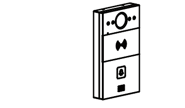 | R20A .. 1x | 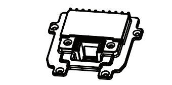 | 1x | 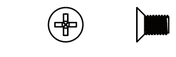 | M2.5x6 .. 6x |
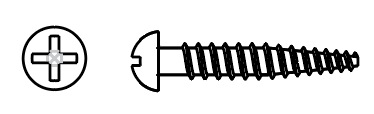 | ST4x20 .. 4x | 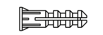 | 4x | 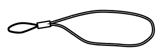 | 1x |
 | 1x | 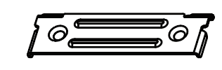 | 1x | 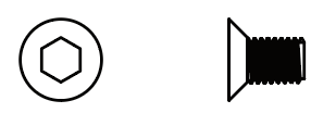 | M3x6 .. 2x |
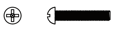 | M4x30 .. 2x | 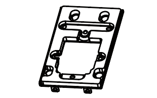 | 1x | ||
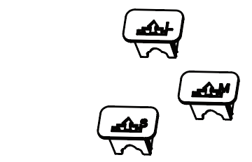 | 3x | 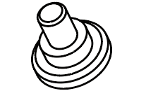 | 4x |
Installation of wall mounting fixture
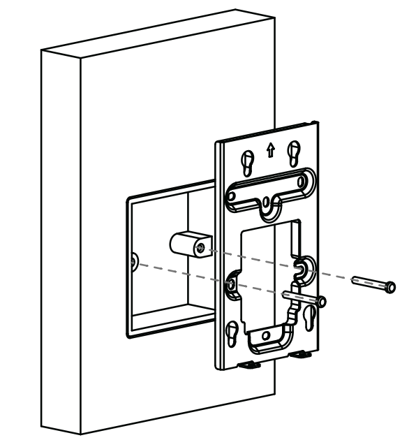
Fix the wall-mounting bracket on embedded box with two M4x30 screws.
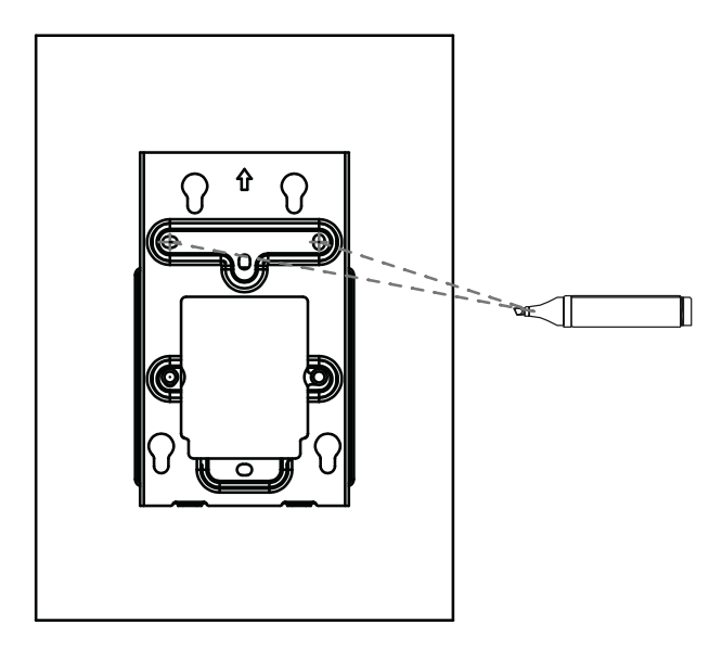
Mark the two holes of the mounting bracket on the wall.
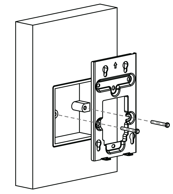
Take down two M4x30 screws and remove the wall-mounting bracket.
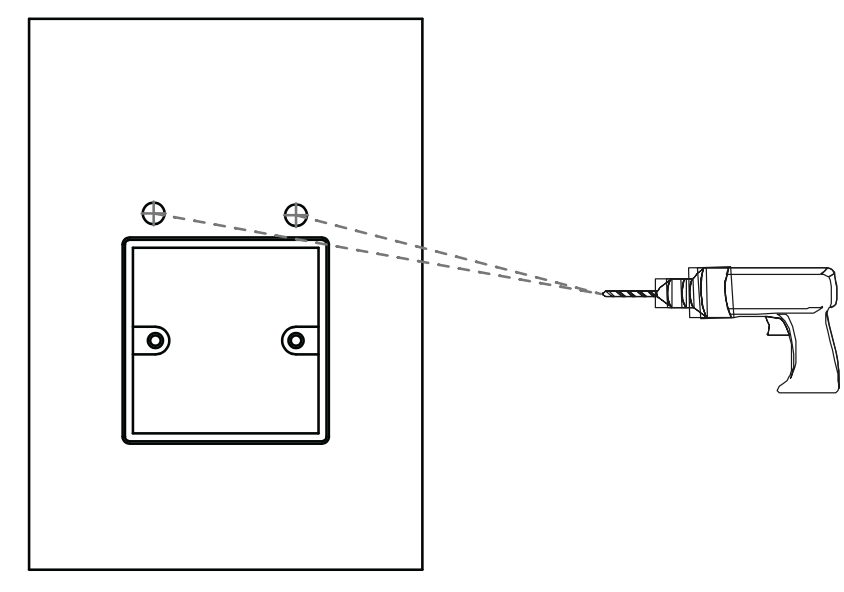
Use a drill bit with 5 mm diameter to make two 25 mm depth holes in the marked positions.
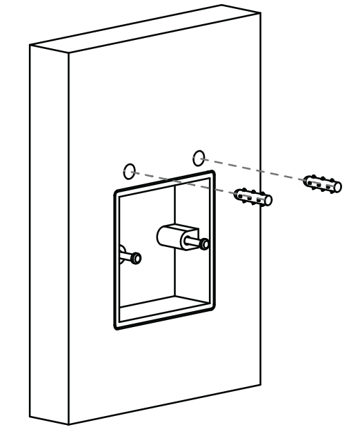
Insert two screw dowels into the holes.
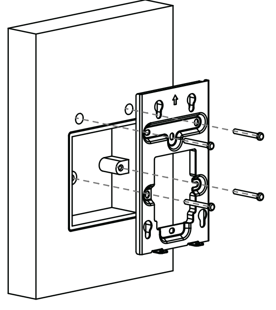
Fix the wall-mounting bracket with two ST4x20 screws and two M4x30 screws.
Installation of back cover
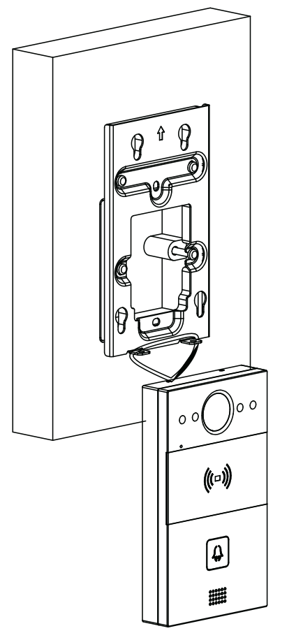
For convenient wiring, hang R20A on the wall mounting bracket with rope.
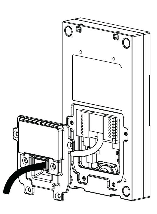
Make cables go through the back cover, connecting to the corresponding interfaces of the main board.
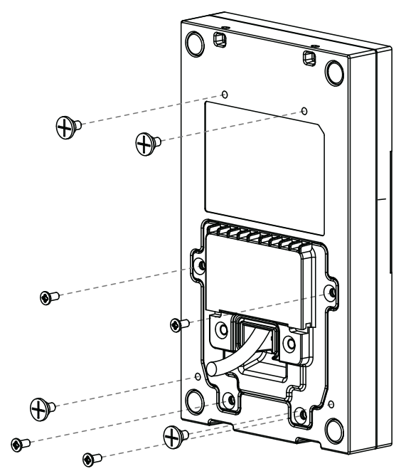
Fasten the back cover with four M2.5x6 screws, then fix four wall mounting screws on the back of R20A.
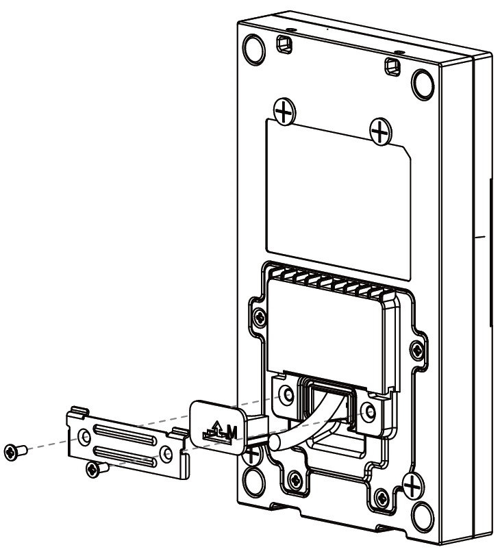
Select a suitable size rubber plug to push all the cables into the back cover. Fix cable locking plate to the back cover with two M2.5x6 screws.
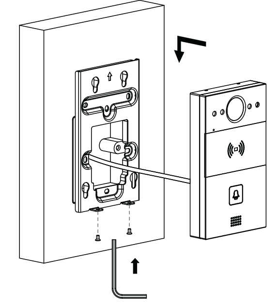
Insert the four wall-mounting screws on the device into the corresponding holes on the mounting bracket, and then press down to slide the wall-mounting screws into the groove. Then use the allen wrench to tighten the device with two M3x6 screws.
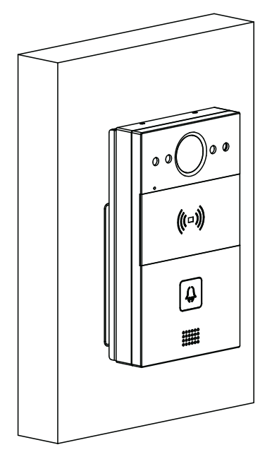
After successful installation, check stability of the device.
See the original manual [EN]