CT Clamp — Current Measurement via Analog Input
How to connect a CT clamp (current transformer) with 0-10V output to TapHome universal input for continuous current measurement.
A CT clamp (current transformer) with a 0–10 V output allows you to measure current on individual circuits in the electrical panel — without disconnecting any wires. The CT clamp wraps around a single conductor, detects the current flowing through it using a Hall-effect sensor, and outputs a proportional 0–10 V signal that is read by a TapHome universal input (UI) in analog mode.
When to use a CT clamp vs. a Modbus electricity meter:
A CT clamp is the right choice when you need continuous current measurement on a single circuit (per breaker) — for example, to detect whether a specific appliance is running. For full energy monitoring (voltage, current, power, power factor, frequency, cumulative kWh), consider a Modbus RTU electricity meter instead. Modbus meters provide significantly more data, are more accurate, and integrate directly with TapHome via the bus.
See the list of supported electricity meters in the Compatibility list — Electric meter section.
Choosing a CT clamp
To work with TapHome universal inputs, the CT clamp must meet these requirements:
| Requirement | Value |
|---|---|
| Output signal | 0–10 V DC (linear, proportional to current) |
| Supply voltage | 24 V DC (same source as TapHome modules) |
| Type | Split-core (can be installed without disconnecting the conductor) |
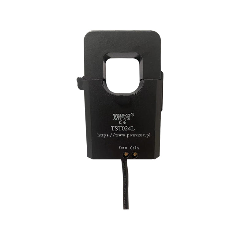
Recommended product: YHDC TST024L
The YHDC TST024L is a split-core Hall-effect current transducer with a 0–10 V output, available in multiple current ranges.
| Parameter | Value |
|---|---|
| Current ranges | 100 A, 150 A, 200 A, 250 A, 300 A |
| Measuring range | up to 120% of rated current |
| Output | 0–10 V DC (proportional) |
| Supply voltage | +24 V DC (±5%) |
| Accuracy | 0.5% |
| Linearity | 0.5% |
| Response time | ≤ 200 ms |
| Bandwidth | 50–400 Hz |
| Dielectric strength | 2.5 kV (50 Hz, 1 min) |
| Core opening | Ø 24 mm |
| Dimensions | 53 × 75 mm |
| Weight | 201 g |
| Cable | 3-wire shielded, 50 cm (red = +V, black = GND, green = signal) |
| Operating temperature | −10 to +70 °C |
| Price | ~18 EUR |
Choosing the right current range: Select a range that matches the breaker protecting the circuit. For a 16 A breaker (typical for a socket circuit), a 100 A CT is more than sufficient. For a 63 A breaker (e.g., heat pump), choose 100 A or 150 A to stay well within the linear range.
Alternative: SENECA T201DCH
For installations requiring higher accuracy (0.5% AC / 1% DC), DC current measurement, or DIN-rail mounting, consider the SENECA T201DCH series (~60–115 EUR). The T201DCH also measures DC current (TRMS) and is available with Modbus output (T201DCH-M variant).
Wiring
The CT clamp has a 3-wire shielded cable (50 cm) with color-coded wires:
- Red — power supply (+24 V)
- Black — ground (GND)
- Green — signal output (0–10 V)
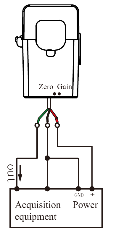
In the diagram above, “Power” is the 24 V DC power supply and “Acquisition equipment” is the TapHome module. The three connections are:
| CT clamp wire | Connect to | Description |
|---|---|---|
| Red (+V) | 24 V DC power supply + terminal | Powers the Hall-effect sensor inside the CT |
| Black (GND) | 24 V DC power supply − terminal | Common ground — must also be connected to TapHome module GND |
| Green (signal out) | TapHome module UI input terminal | Analog 0–10 V signal proportional to measured current |
The black GND wire connects to the power supply’s negative terminal, which must be shared with the TapHome module’s GND. This creates a common voltage reference for the 0–10 V signal.
Common ground is essential. The CT clamp and the TapHome module must share the same 24 V DC power supply (or at least have their GND terminals connected together). Using separate power supplies without a common ground reference will result in incorrect or erratic readings.
Important rules
- One conductor only — clamp the CT around a single conductor (the phase wire L), never around the entire cable. If you clamp around L + N together, the magnetic fields cancel out and the reading will be zero.
- Arrow direction — the arrow printed on the CT clamp body indicates the expected direction of current flow. If you get negative or zero readings, flip the CT clamp 180°.
- Keep cables short — the 0–10 V signal cable between the CT and the TapHome module should be as short as possible (ideally < 5 m) to minimize electromagnetic noise pickup.
- Galvanic isolation — the CT clamp has built-in galvanic isolation rated at 2.5 kV (50 Hz, 1 min). No additional optical or galvanic isolation is needed for standard residential panel installations.
- Zero & Gain pots — the CT clamp has two calibration potentiometers labeled “Zero” and “Gain” on the housing. These are factory-calibrated. Do not adjust them unless you have a reference current source for recalibration.
TapHome modules with analog input
All TapHome modules with universal inputs (UI) support analog 0–10 V mode. The key difference is ADC resolution:
| Module | Type | ADC resolution | Voltage range | Input impedance |
|---|---|---|---|---|
| 2 UI | Flush-mount | 8-bit (256 steps) | 0–12 V | > 16 kΩ |
| 6 UI | Flush-mount | 8-bit (256 steps) | 0–12 V | > 16 kΩ |
| 6 UI / 6 OC | Flush-mount | 8-bit (256 steps) | 0–12 V | > 16 kΩ |
| 6 UI / 6 UO | Flush-mount | 8-bit (256 steps) | 0–12 V | > 16 kΩ |
| 4 UI / 2 DO | Flush-mount | 8-bit (256 steps) | 0–12 V | > 16 kΩ |
| 32 UI | DIN rail | 12-bit (4096 steps) | 0–26 V | > 10 kΩ |
| 12 DO 12 UI | DIN rail | 12-bit (4096 steps) | 0–26 V | > 100 kΩ |
Resolution matters for current measurement. With a 200 A CT clamp:
- 8-bit module → resolution of ~0.8 A per step (sufficient for detecting on/off states)
- 12-bit module → resolution of ~0.05 A per step (suitable for precise monitoring)
For energy monitoring applications, we recommend using a DIN-rail module (32 UI or 12 DO 12 UI) with 12-bit ADC resolution.
Configuration in TapHome app
Step 1: Enable the analog input
- Go to Settings → Hardware → TapHome Bus
- Select the module that has the CT clamp connected
- In the Universal inputs section, select a free input (e.g., UI3)
- Under Function, select Analog input
- Assign a zone and category, then save
The input will now show a value in percent (0–100%), representing the raw voltage as a percentage of the configured range. For example, 1.5 V on a 0–10 V input displays as 15%.
Step 2: Add value conversion to amperes
Without conversion, the analog input only shows a percentage — not useful for current measurement. To display the value in amperes:
- Open the service settings of the analog input device
- In the Value conversion section, tap Add value conversion
- Select Analog input → Electric current [A]
Step 3: Configure linear interpolation
After adding the conversion, a Linear interpolation section appears. This maps two input/output points to create a linear scale between voltage and current.
The default mapping is 0–10 V → 0–10 A. You need to change the output to match your CT clamp’s rated current:
For a 200 A CT clamp (YHDC TST024L-200A):
| Setting | Value |
|---|---|
| Input value 1 | 0 (0%) |
| Output value 1 | 0 (0 A) |
| Input value 2 | 10 (1000%) |
| Output value 2 | 200 (200 A) |
The CT clamp outputs 0 V at 0 A and 10 V at its rated current. By setting output value 2 to the rated current of your CT, the system correctly scales the voltage reading to amperes.
The input values (0 and 10) correspond to the Minimum voltage (0 V) and Maximum voltage (10 V) configured in the Other section below. Leave these at their defaults (0 V and 10 V) for standard CT clamps.
Step 4: Verify the reading
After saving, the dashboard will show the measured current in amperes instead of a percentage. Turn on a known load (e.g., a 2 kW heater ≈ 8.7 A at 230 V) to verify the reading is correct.
For a general overview of conversion functions and other use cases (water level, rain gauge, electricity cost), see Conversion Functions.
Calculating power and energy consumption
The CT clamp measures current (A). To calculate power (W) and energy (kWh), you need to account for the voltage and power factor:
Power formula:
P = U × I × cos(φ)
Where:
- P = active power (W)
- U = voltage (≈ 230 V for single-phase in Europe)
- I = measured current (A)
- cos(φ) = power factor (0.95–1.0 for resistive loads like heaters, 0.5–0.8 for motors)
For a simplified calculation with resistive loads, you can use:
P ≈ 230 × I
To track cumulative energy (kWh), create a virtual device in TapHome using an Equation Smart Rule that integrates the power over time.
Troubleshooting
| Symptom | Possible cause | Solution |
|---|---|---|
| Reading is always 0 | CT not powered | Check 24 V supply to CT (red/black wires) |
| Reading is always 0 | No current flowing | Verify load is on; check CT is on the correct conductor |
| Negative values | CT clamp reversed | Flip the CT clamp (reverse the arrow direction) |
| Value stuck at maximum | Current exceeds CT range | Choose a CT with a higher rated current |
| Noisy / fluctuating reading | Ground loop or long cable | Ensure common GND; shorten the signal cable; use shielded cable |
| Reading is inaccurate | Wrong conversion formula | Re-check min/max values in the conversion setup |